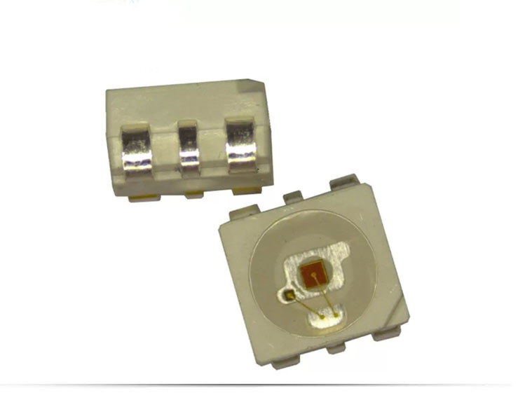
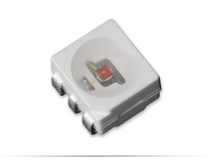
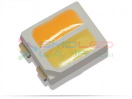
0.5W 620-630NM Red Color 3433 Smd Led 15-20LM For Automotive Led Light Source
Product Details:
Place of Origin: SHENZHEN
Brand Name: Yuhang
Certification: CE.SGS.ROHS
Model Number: YH3433R
Payment & Shipping Terms:
Minimum Order Quantity: 10K
Price: Please inquiry
Packaging Details: 1000pcs/Reel our product package size is 25x23CM, and is the use of aluminum vacuum packaging. And different types of containers, small cartons can be installed about 100K products. Large box can hold about 500K.
Delivery Time: 5-7 work days
Payment Terms: T/T, Western Union,Paypal
Supply Ability: 8KK/Days
Detailed Product Description
| Type: | Rgb Power Led | Emitting Color: | Red |
|---|---|---|---|
| Luminous Flux(lm): | 15-20LM | Power: | 0.5W |
| Viewing Angle(°): | 120 Degree | Color Rendering Index: | Null |
| Color Temperature: | 620-625nm | Chip Brand: | Epistar Chip, Sanan Chip,Epileds Chip |
| Current: | 150mA | Voltage: | 2.0-2.4V |
0.5W 620-630NM Red color 3433 smd led for automotive led light source
Features
· SMD packaging high power led type.
· Compact design 3 in 1/4 in 1 RGB-W-W LEDs
· Exclusive chip source & Unique phosphor coating technology
· Super small space between chips offering outstanding color mixing performance.
· Outdoor landscape lighting, stage lighting, smart lighting, etc.
Applications:
Automotive: Backlighting in dashboards and switches.
Telecommunication: Indicator and backlight in telephone and fax
Indicator and backlight for audio and video equipment.
Indicator and backlight in office and family equipment.
Flat backlight for LCD’s, switches and symbols.
Light pipe application.
General use.
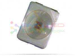
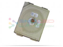
| Part No. | Chip Material | Lens Color | Source Color |
| YH3433R | AlGaInP | Water Clear | Red |
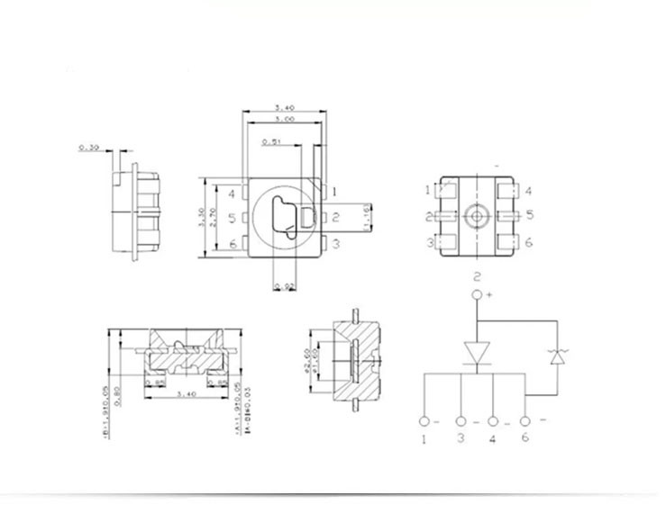
| SURFACE MOUNT LED LAMPS | |||||||||
| Product Type:YHR3433 | |||||||||
| Absolute maximum ratings (Ta=25°C) | |||||||||
| Parameter |
Symbol |
Value | Unit | ||||||
| Forward current |
If |
150 | mA | ||||||
| Reverse voltage | Vr | 5 | V | ||||||
| Power dissipation | Pd | 0.38 | W | ||||||
| Operating temperature range | Top | -25~+80 | °C | ||||||
| Storage temperature range | Tstg | -30~+85 | °C | ||||||
|
Peak pulsing current (1/8 duty f=1KHz) |
Ifp | 200 | mA | ||||||
| Electro-Optical characteristics (TA=25°C) | |||||||||
Parameter |
Test Condition |
Symbol |
Value | Unit | |||||
| Min | Typ | Max | |||||||
| Color Temperature | -- | CCT | -- | -- | - | K | |||
| Forward voltage | If=150mA | Vf | 2.0 | -- | 2.4 | V | |||
| luminous flux |
If=150mA |
φ | 15 | -- | 20 | LM | |||
|
Viewing angle at 50% IV |
If=150mA | 2θ1/2 | -- | 120 | -- | Deg | |||
|
Dominant wavelength |
If=150mA |
λd | 620 | -- | 630 | nm | |||
| Reverse current | Vr=5V | Ir | -- | 5 | -- | μA | |||
Notes:
Luminous Intensity Measurement allowance is ± 10%.
θ1/2 is the off-axis angle at which the luminous intensity is half the axial luminous intensity.
It use many parameters that correspond to the CIE 1931 2°. X, Y, and Z are CIE 1931 2° values of Red, Green and Blue content of the measurement.
Please read the following notes before using the product:
Over-current-proof
Customer must apply resistors for protection, otherwise slight voltage shift will cause big current change (Burn out will happen).
Storage
2.1 Do not open moisture proof bag before the products are ready to use.
2.2 Before opening the package, the LEDs should be kept at 30℃ or less and 90%RH or less.
2.3 The LEDs should be used within a year.
2.4 After opening the package, the LEDs should be kept at 30℃ or less and 70%RH or less.
2.5 The LEDs should be used within 168 hours (7 days) after opening the package.
2.6 If the moisture adsorbent material (silica gel) has fabled away or the LEDs have exceeded the storage time, baking treatment should be performed using the following conditions. Baking treatment: 60±5℃ for 24 hours.
Soldering Condition
3.1 Pb-free solder temperature profile.
3.2 Reflow soldering should not be done more than two times.
3.3 When soldering, do not put stress on the LEDs during heating.
3.4 After soldering, do not warp the circuit board.
Soldering Iron
Each terminal is to go to the tip of soldering iron temperature less than 260℃ for 5 seconds within once in less than the soldering iron capacity 25W. Leave two seconds and more intervals, and do soldering of each terminal. Be careful because the damage of the product is often started at the time of the hand solder.
Repairing
Repair should not be done after the LEDs have been soldered. When repairing is unavoidable, a double-head soldering iron should be used (as below figure). It should be confirmed beforehand whether the characteristics of the LEDs will or will not be damaged by repairing.
Caution in ESD
Static Electricity and surge damages the LED. It is recommended to use a wrist band or anti-electrostatic glove when handling the LED. All devices, equipment and machinery must be properly grounded.
INQUIRY
CATEGORIES
CONTACT US
Contact:Vicky
WhatsApp/Wechat:86-13410359515
E-mail:info@smdledlamp.com
Add:5B13-1, Futian Market Building, Fuhua Road, Futian District, Shenzhen